See further info here: http://www.sydneymetro.info/
Project Overview
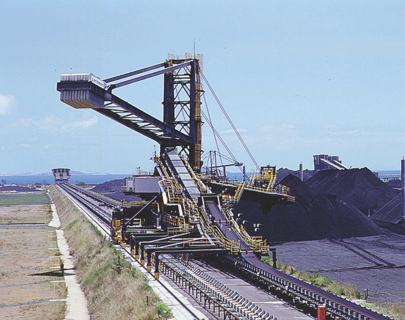
In September 2008 Theiss, contracted by NCIG, began the construction of a component section of a brand new industrial Coal Export Terminal (CET) worth $105 million on Kooragang Island.
Theiss’s small but integral part of the $1 billion project demanded the construction and installation of inbound systems, a coal stockyard as well as other civil, structural and mechanical works. NCIG took less than two years to build and now stands a state-of-the-art industrial facility that can process 30 million tonnes of coal per year.
EDC’s role
EDC was sub-contracted by Theiss to be the major drafting company responsible to collaborate with Theiss engineers in both the design and planning processes of the NCIG project. EDC’s contract demanded it provide the following roles, responsibilities and deliverables for the project:
• Detail design of all lifting processors for the conveyers, dump stations and buffer bin
• Design review of all detail drawings to ensure the correct material was used by the structural steel detailers
• Detail drafting services for various parts of the project and especially for the complex buffer bin
• Material take-off for all the design changes
Project outcome
The creation of the CET (NCIG) resulted in a world-leading industry facility that has enabled the vast increase of Newcastle’s coal export capacity; further enhancing the capabilities of Australia’s most-active deep-water port and helping it to maintain its status of No.1 coal port in the world. Its creation has since helped to increase GDP by $1.5 billion a year, increase exports by upwards of $2 billion a year, and generated 5000 jobs.
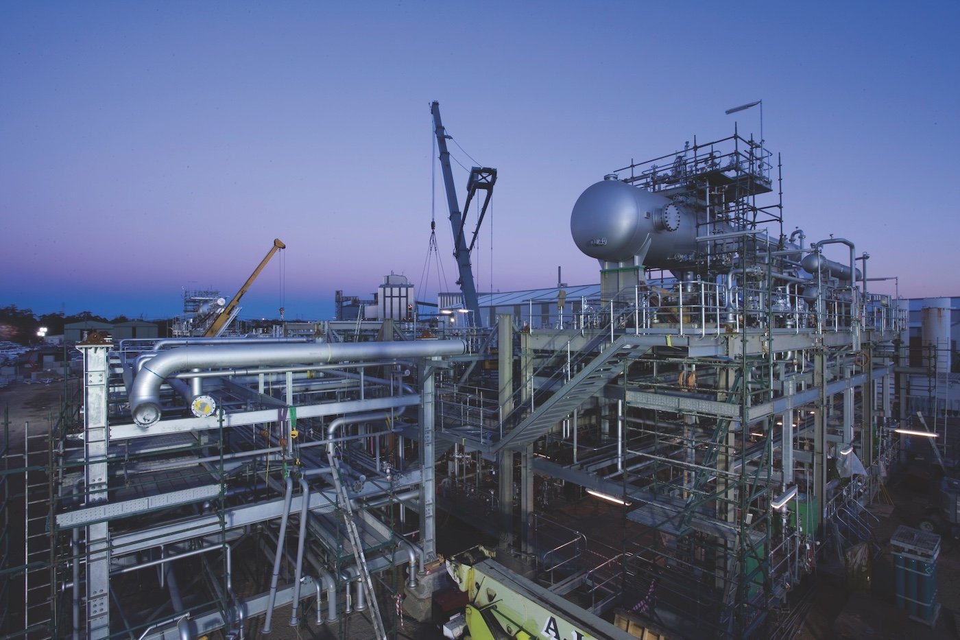
This project consisted of two processing plants, which when combined, were constructed from 38 individual modules. These were erected and tested prior to being shipped to their final destinations.
Processing Plant 1 weighed 350 tonnes and Processing Plant 2 weighed 318 tonnes. The modules consisted of large columns and floor beams which had extensive bracing throughout. Most of the modules also contained the access platforms, stairs, caged ladders, handrailing and grating.
The two processing plants comprised individual modules which were assembled and erected on the site where the fabrication had taken place. All steelwork, piping, fire proofing insulation and other finishings were installed, checked and tested.
The processing plants were then dismantled into their individual modules in preparation for being shipped to their destination by an ocean-going barge. Once at the site they were re-assembled and made ready to commence their operation
The accuracy of the positioning and set-out of the modules was vital due to the mechanical and piping components made to fit. One of the successful and key advantages to the modular project was the technology invested by EDC Pty Limited who used Bocad software.
This innovative 3D parametric modelling software is designed in such a way that a 3D element or member is not just an object drawn in a three dimensional environment. The members created have valuable data information which consultants can use in their design process. The data attached to the members include: dimensional profile of the member, grade, mass, section and surface area, second moment of inertia, section modulus, moment arm etc.
The advancement in this technology allows designers, manufacturers and detailers to communicate on a common ground through electronic data files such as SDNF, PDMS, CNC and DXF. On this project, the designer exported their modules from PDMS (Plant Design Modelling System), which is also 3D parametric, directly into the Bocad system for the detailer to complete the works required in the 3D project model. This information was then exported back into PDMS, which the designers found to be extremely useful as they were able to check and review their design against the detailer’s 3D model at each stage. This gave them the opportunity to confirm that all of the design criteria was complete and also to compare with other objects in their design to prevent any clashing from occurring.
At the manufacturing stage the fabricators were supplied with CNC (Computer Numerical Control) and DXF (Drawing Exchange Format) files. This enabled the fabricator to embrace robotics with methods such as ‘Beam line’ and ‘Laser cutting’ technologies for the cutting and drilling of the steel beams, channels and angles used. This increased the accuracy and speed of manufacture, as well as productivity and efficiency on the project.
All design reviews were done through the process of exporting and importing 3D models. Structural detail drawings were not required to be reviewed by consultants. They were created as pdfs and issued via e-mail through electronic data transfer.
The manufacturers/fabricators also received lists/reports on the project:
• Assembly list (a list of assemblies along with their associated fittings)
• Fittings/small parts List (a list of the fittings with reference to all associated assemblies)
• Cutting list (cut lengths of members in member type category)
• Cut-off list (bevel, notching or other types of cuts for beams, channels and angles required)
• Bolts list (quantity and types of bolts and garnishing required over all)
• Bolts connectivity list (bolts required to each assembly member for site erection).
All the lists were produced in various electronic data file formats, the most commonly used were pdf and Excel.
The Bocad model was also exported into various types of viewers, such as Deep viewer, 3D pdf and IFC. These viewers were used to show the structure in simulation and allowed the various parties involved in the project to have access to the model. By utilising the filter function they could then elect to see only the areas of interest to them and select any required items.
One of the key advantages of this was with the on site erection, providing the construction team a wealth of information, including being able to identify the various assemblies’ orientation and location quickly and easily


